Lee Ultrasound Imaging Group
Department of Electrical and Electronic Engineering
The University of Hong Kong
Research
Preface Thanks to its real-time feature and inexpensiveness, medical ultrasound is still the predominant noninvasive imaging modality in the clinic. Conventional ultrasound imaging illustrates the anatomy and the structure of tissues/organs. Our lab currently focuses on ultrasound imaging methodologies that offer quantitative measurement of living tissue function.
Ultrasound Strain Imaging
Ultrasound strain imaging has emerged in the last two decades for the detection of tissue abnormalities, such as the tumor. It has also been extensively investigated for the diagnosis of cardiovascular disease by quantifying the deformation of heart muscle and arterial walls. Our lab aims at developing ultrasound strain imaging techniques to accurately examine the kinematics of living tissues. In brief, ultrasound strain imaging estimates displacements, from which strains are derived.
Example 1:
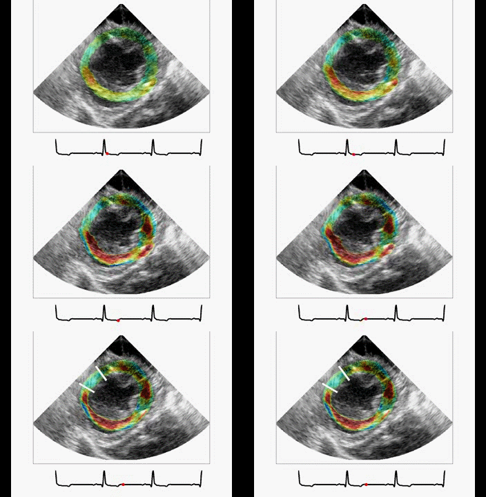
The animations and images below show the full strain-tensor maps of a beating porcine heart obtained using our high-frame-rate cardiac ultrasound strain imaging framework. Each strain component of the heart muscle is color-coded and overlaid on the ultrasound images of the heart. For the radial and circumferential strains, the red and blue colors indicate the heart wall thickening and thinning, respectively. For the shear strain, the read and blue colors indicate the bidirectional sliding of the heart muscle layers. Good agreement has been achieved between our results and that derived from displacement-encoded MRI reported in a previous study.
Radial Strain 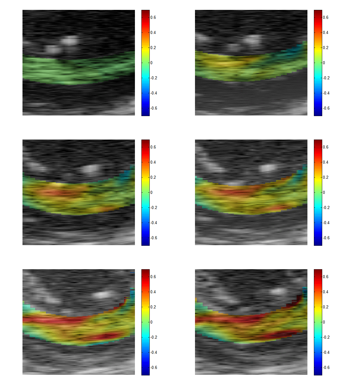 |
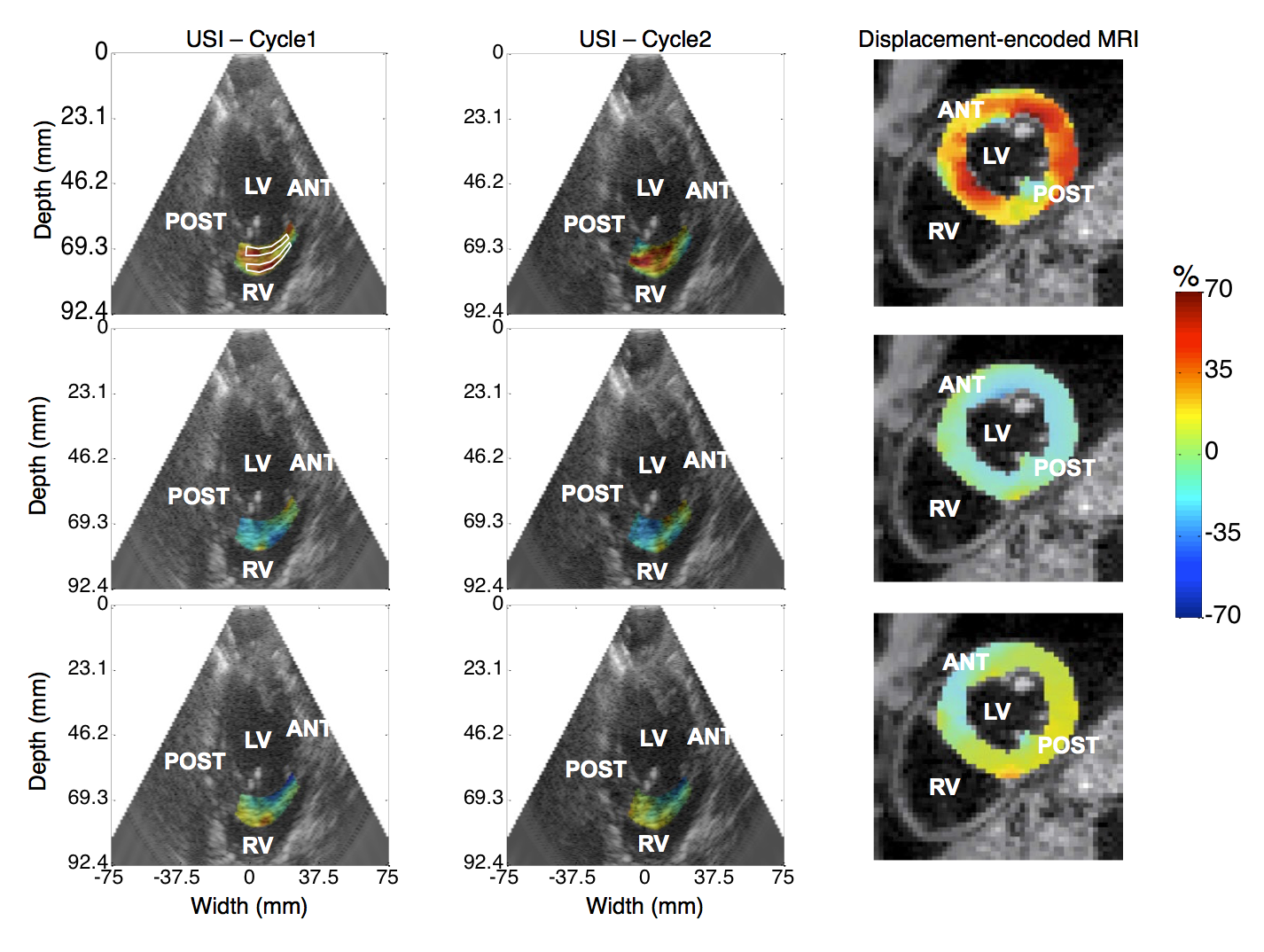 |
|
Circumferential Strain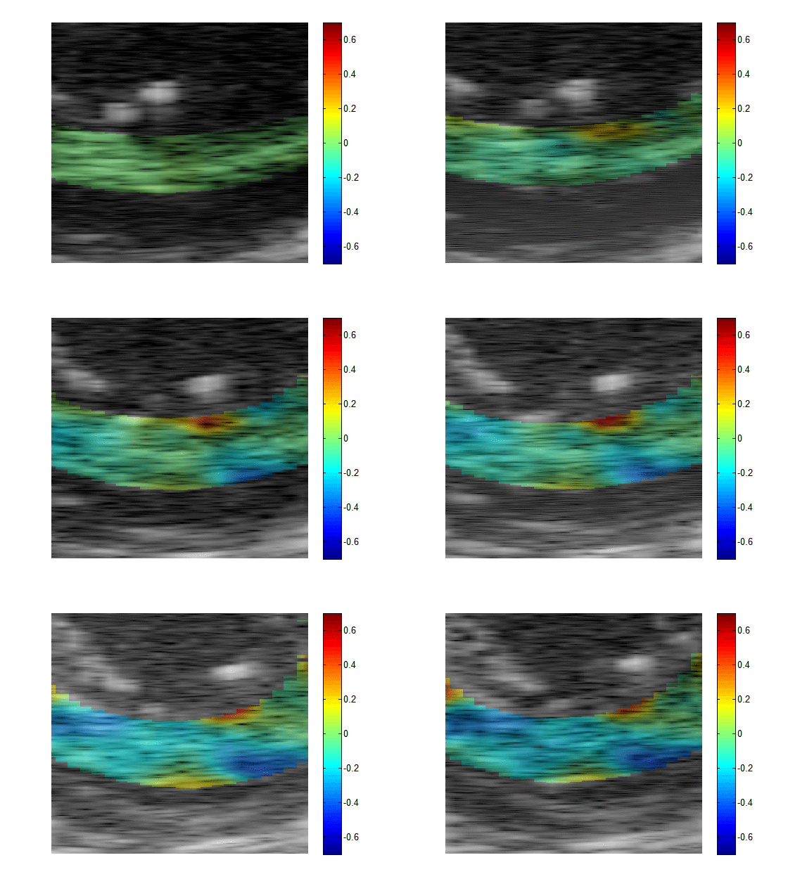 |
||
Radial-Circumferential Shear Strain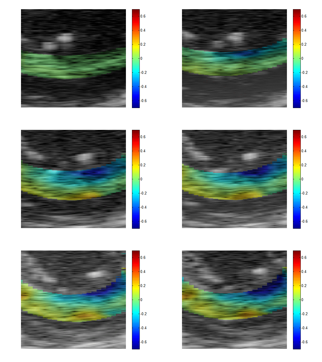 |
||
Example 2:
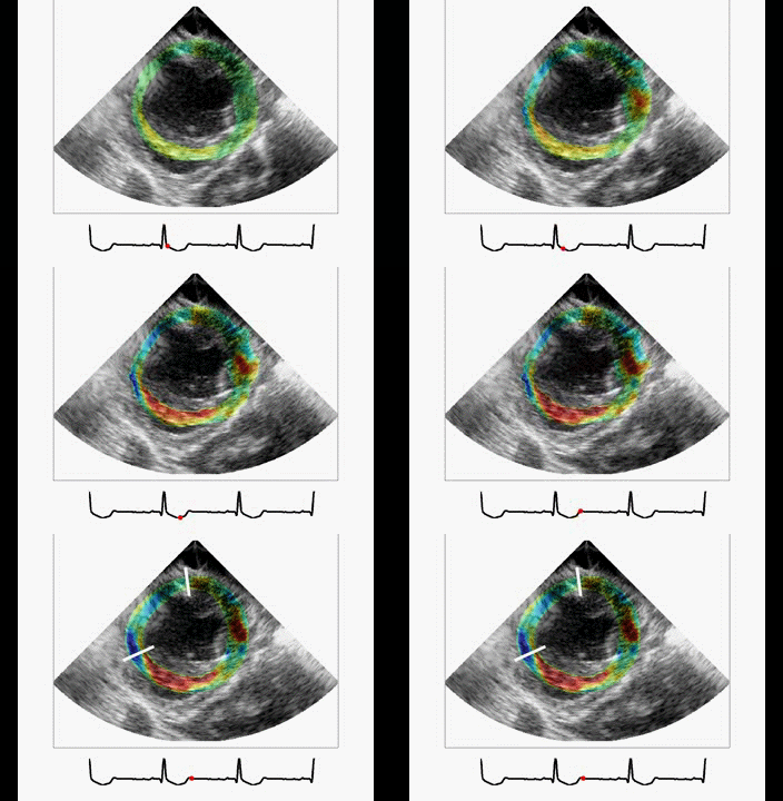
The animations below show the full strain-tensor maps of a beating porcine heart obtained using our high-frame-rate cardiac ultrasound strain imaging framework. Each strain component of the heart muscle is color-coded and overlaid on the ultrasound images of the heart. For the radial and circumferential strains, the red and blue colors indicate the heart wall thickening and thinning, respectively. For the shear strain, the read and blue colors indicate the bidirectional sliding of the heart muscle layers.
Radial strain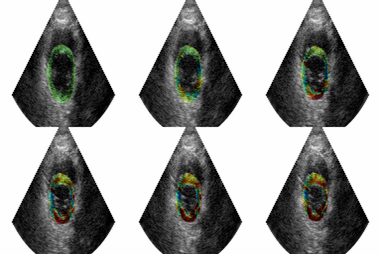 |
Circumferential strain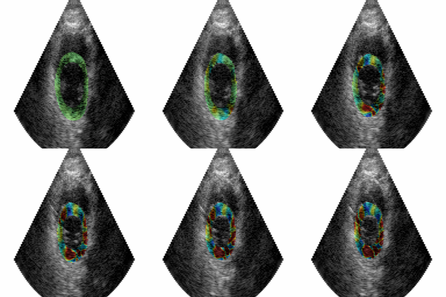 |
Shear strain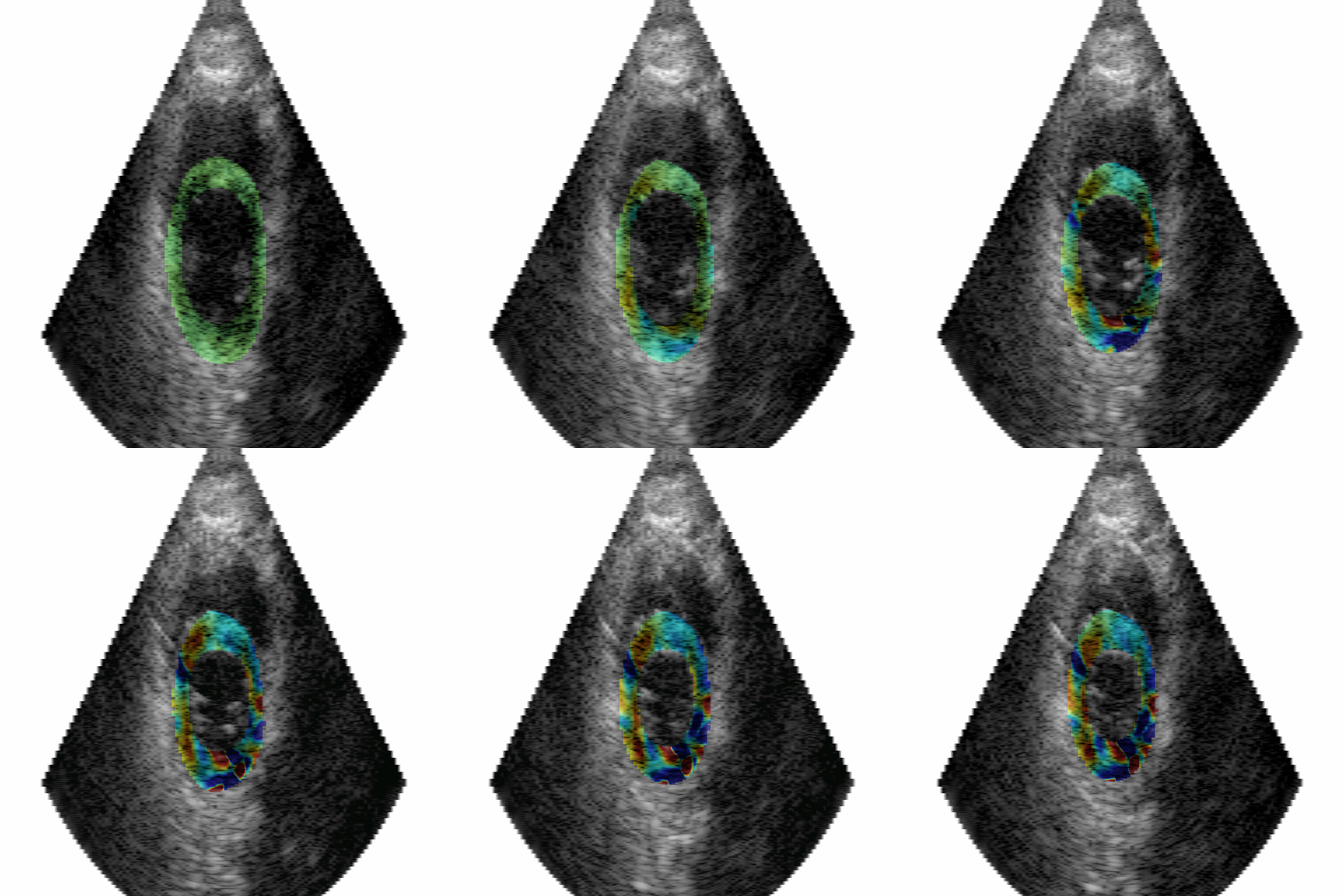 |
Radial vector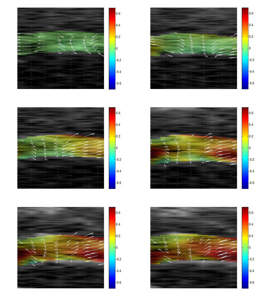 |
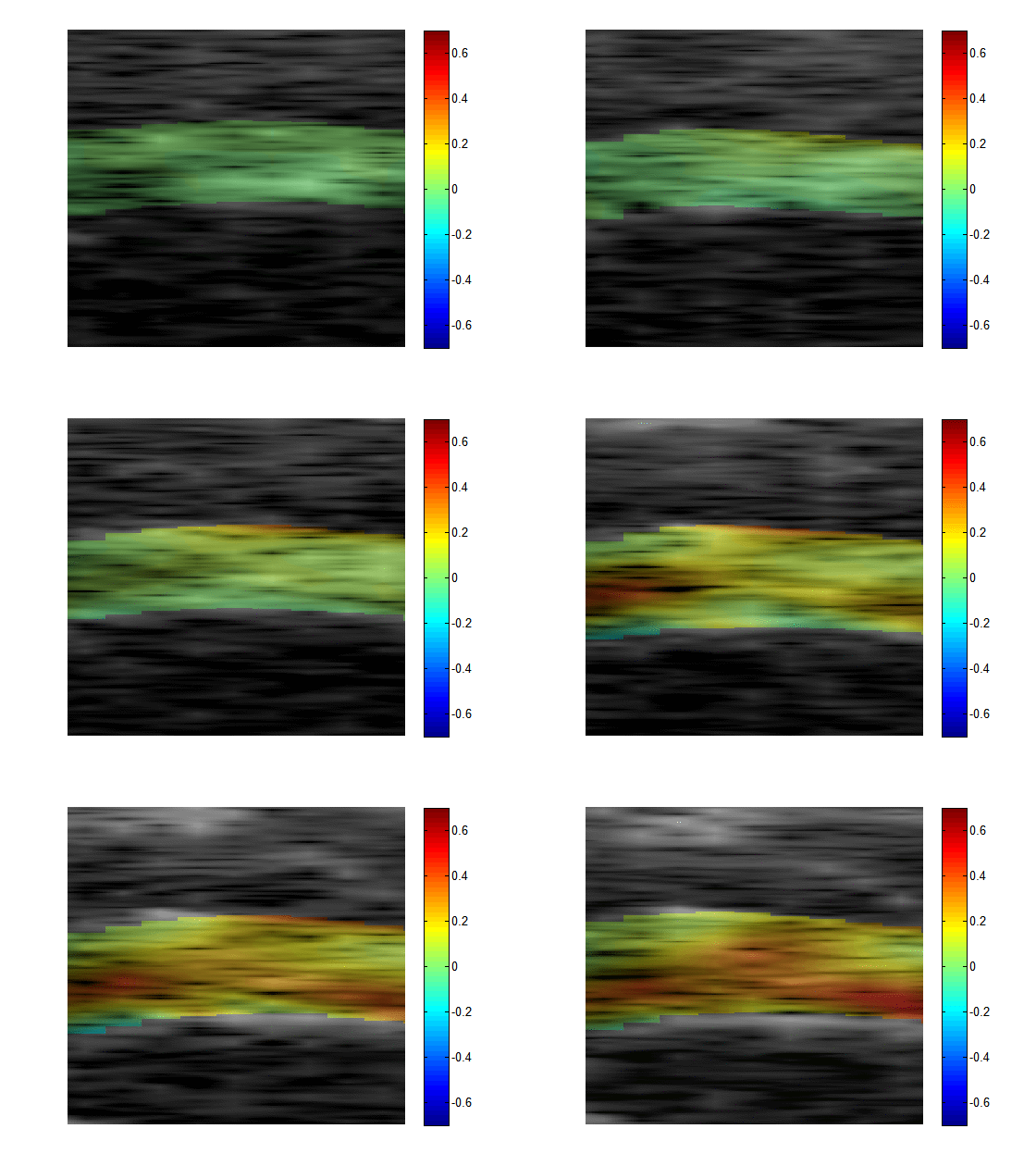 Red color: |
During contraction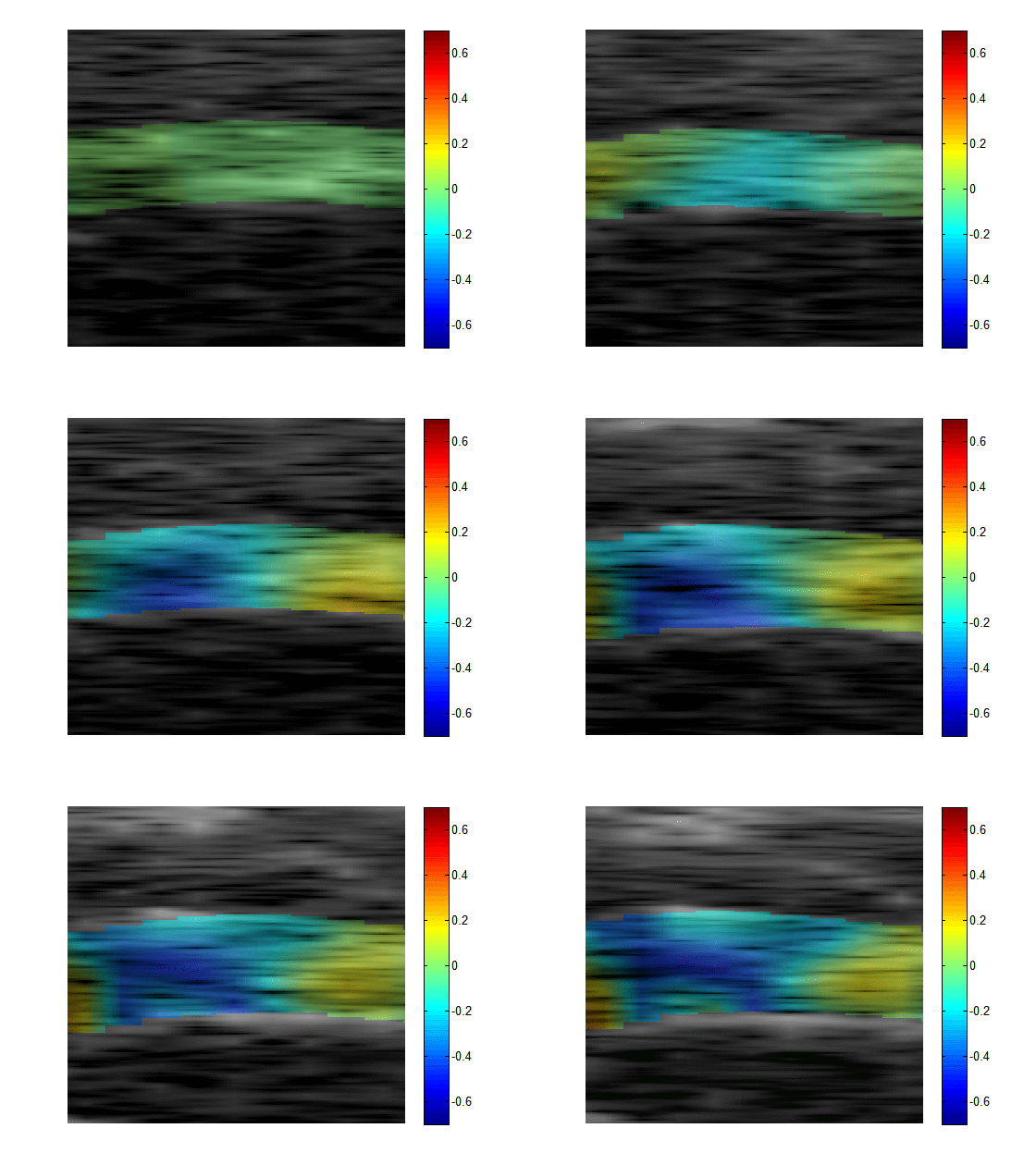 Blue color: |
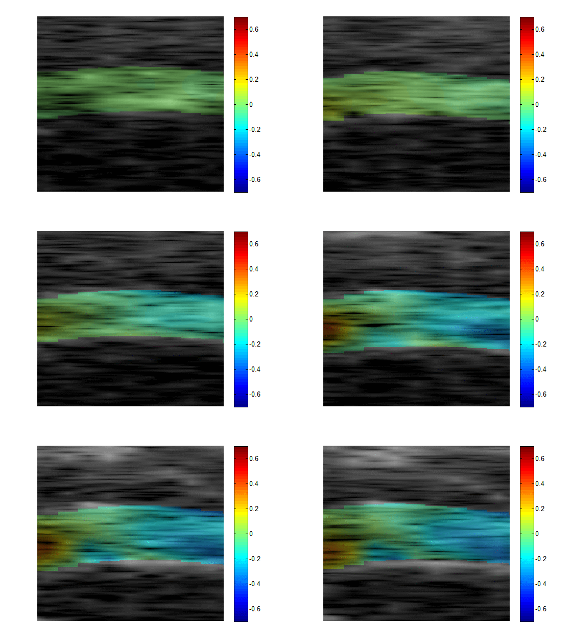 Red & blue: |
Circumferential vector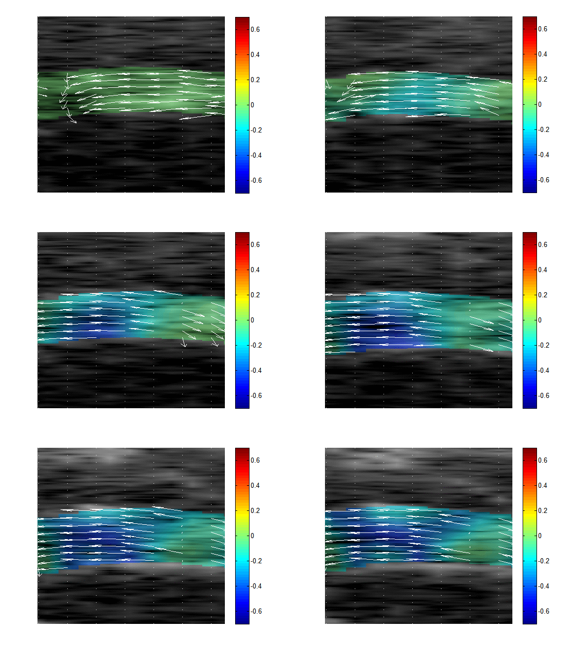 |
Example 3: The carpal tunnel (Liao, Lee, Lee et al., to appear in Radiology 2014)
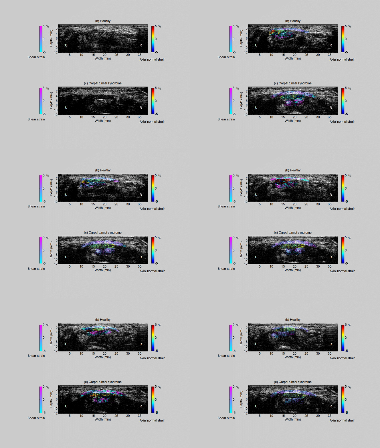
Carpal tunnel syndrome (CTS) is a common entrapment neuropathy resulting from compression of the median nerve at the wrist.The main symptoms include uncomfortable numbness and pain in the wrist and fingers. The abnormality of the median nerve function at the early-stage CTS may not be detected by frequently-used but invasive electrodiagnostic testing. Therefore, we study the feasibilty of ultrasound strain imaging to map the kinematic behavior in the carpal tunnel in noninvasively differentiating diseased from normal conditions. (This work has been performed in collaboration with the research team directed by Professor Chih-Kuang Yeh at National Hsing Hua University in Taiwan)
The movie shows the deformation of the median nerve, flexor retinaculum, and fleor tendons in the human carpal tunnel in normal and diseased conditions.
Example 4: The beating heart (Lee et al., Physics Med. Biol., vol. 56, No. 4, pp. 1155-1172, 2011)
The animations shown below demonstrate the progression of the heart muscle contractility loss under the gradual reduction of the blood supply from the coronary artery in an in vivo large animal model. The radial strain (i.e., deformation) of the heart muscle is color-coded and overlaid on the ultrasound images of the heart. The red and blue colors indicate the heart wall thickening and thinning, respectively. The normal heart should exhibit wall thickening during systole. Therefore, can you point out where the abnormal heart muscle zone is?
0% flow reduction (Baseline) 40% flow reduction
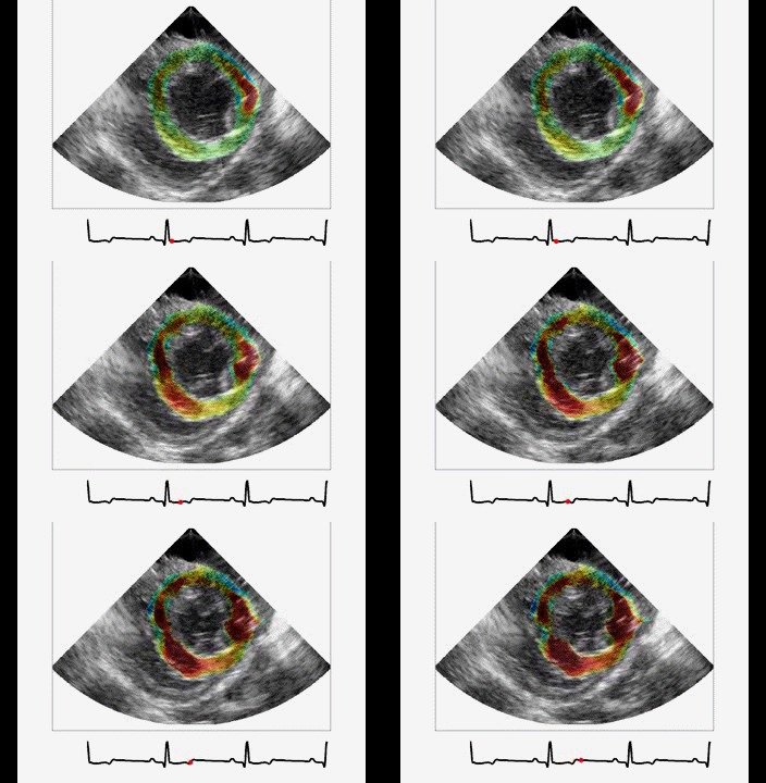
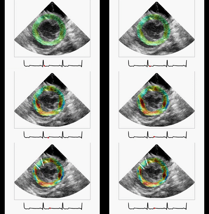
80% flow reduction 100% flow reduction (complete occlusion of the artery)
References:
- W.-N. Lee, J. Provost, K. Fujikura, J. Wang, and E. E. Konofagou, “In Vivo Study of Myocardial Elastography under Graded Ischemia Conditions”, Physics in Medicine and Biology, vol. 56, No. 4, pp. 1155-1172, 2011. (Selected reading listed in 2013 Special Report: ASE Roadmap for 2020)
- W.-N. Lee, Z. Qian, C. L. Tosti, T. R. Brown, D. N. Metaxas, and E. E. Konofagou, “Preliminary Validation of Angle-Independent Myocardial Elastography Using MR Tagging in a Clinical Setting,” Ultrasound in Medicine and Biology, 2008 Dec; 34(12):1980-97.
- W.-N. Lee and E. E. Konofagou, “Angle-Independent and Multi-Dimensional Myocardial Elastography- from Theory to Clinical Validation,” Ultrasonics 2008 Nov; 48(6-7):563-7.
- W.-N. Lee, C. M. Ingrassia, S. D. Fung-Kee-Fung, K. D. Costa, J. W. Holmes, and E. E. Konofagou, “Theoretical Quality Assessment of Myocardial Elastography with In Vivo Validation,” IEEE Trans. Ultrason. Ferroelectr. Freq. Control, Vol. 54, No. 11, pp.2233-2245, 2007.
Shear Wave Imaging
Shear wave imaging has rapidly emerged in the last decade to directly quantify the stiffness of soft tissues as a potential screening tool of cancer. In short, shear wave imaging requires 1) the generation of shear waves propagating inside the tissue using acoustic radiation force; 2) capture of shear waves at ultrafast speed (> 5000 Hz); 3) computation of the shear wave propagation speed, which is directly linked to the stiffness. Different from cancer detection, the example shown below demonstrates how shear wave imaging may be used to map local myofiber orientation noninvasively.
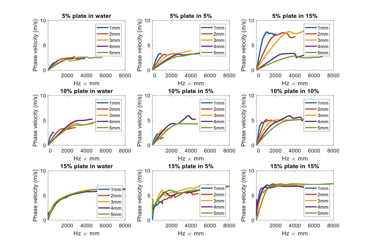
Example1: Effect of the surrounding media on the guided wave propagation in thin media
|
 |
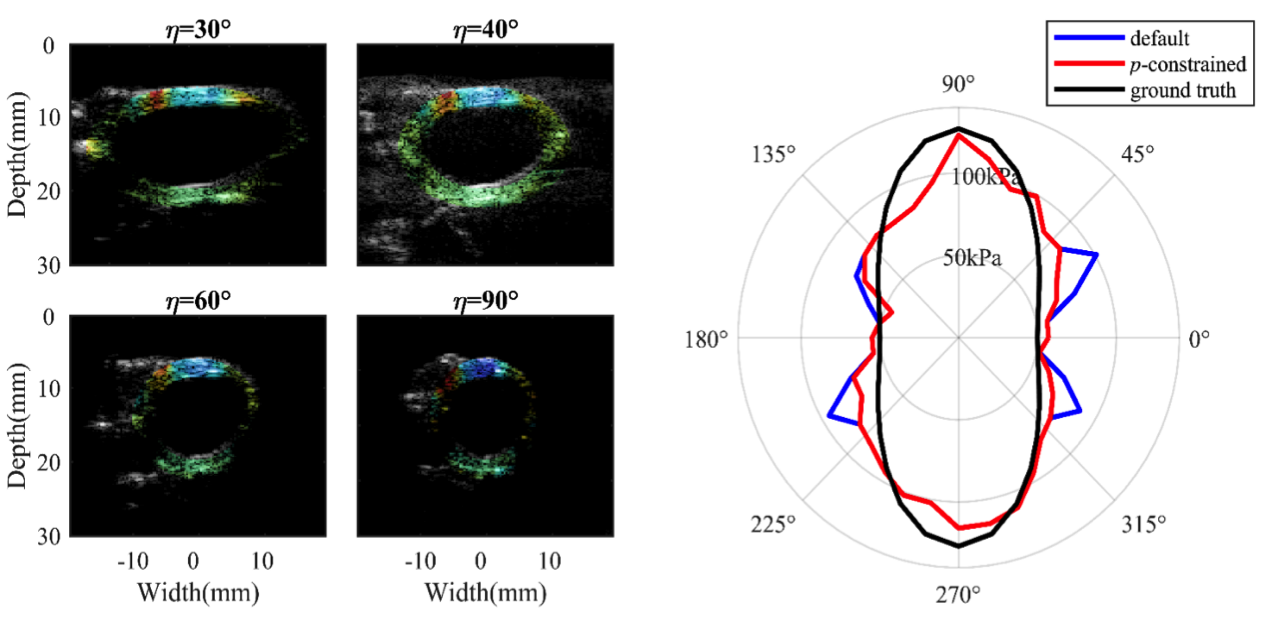
Example2: Multi-directional stiffness estimation of the porcine aorta through guided wave analysis
|
 |
Example3: The heart (Lee et al., IEEE TMI 2012 and PMB 2012)
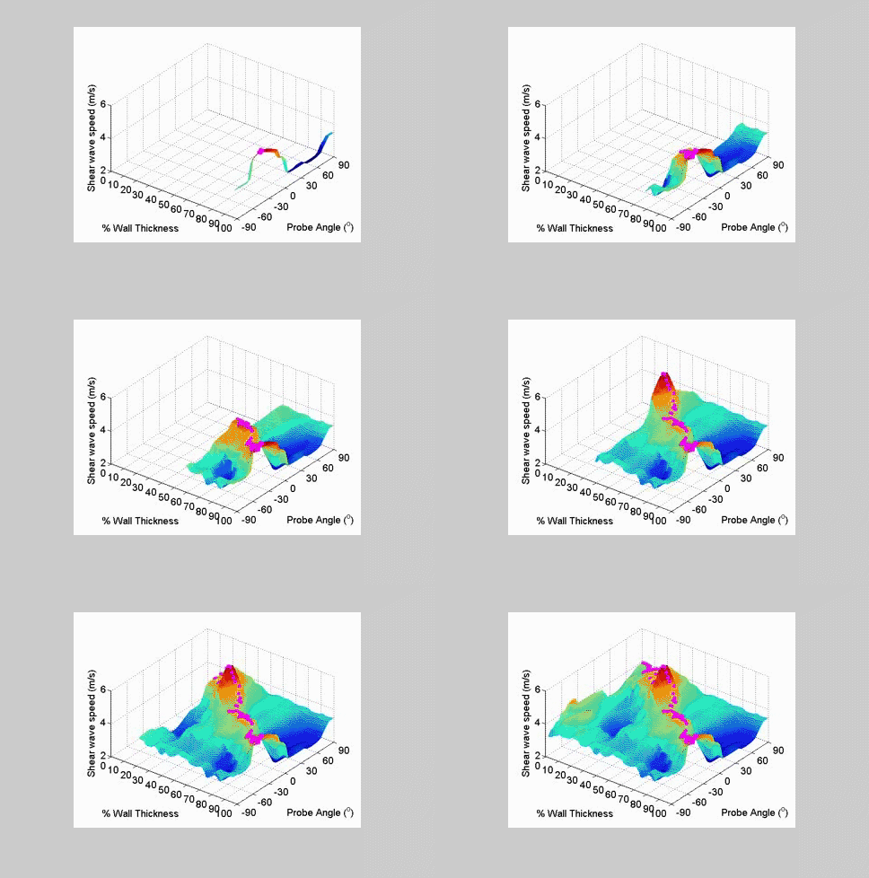
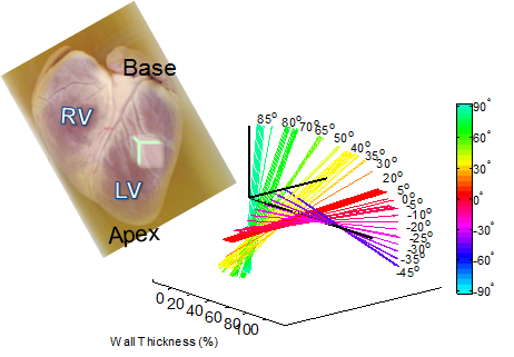
The heart wall is mainly composed of myocytes, which are grouped together into fibers. It has been well documented that these myofibers gradually change their orientations counterclockwise across the wall. Such myocardial fiber structure is associated with cardiac electromechanics and found to be disorganized in hypertrophic cardiomyopathy or post-infarction remodeled hearts. The preliminary results shown here demonstrate that shear wave imaging is capable of measuring and mapping the myofiber orientation in the heart.
References:
- W.-N. Lee, B. Larrat, M. Pernot, and M. Tanter, “Ultrasound Elastic Tensor Imaging: Comparison with MR Diffusion Tensor Imaging in the myocardium,” Physics in Medicine and Biology, vol. 57, no. 16, pp. 5075-5095, 2012. (Featured Article)
- W.-N. Lee, M. Pernot, M. Couade, E. Messas, P. Bruneval, A. Bel, A. A. Hagège, M. Fink, and M. Tanter, “Mapping Myocardial Fiber Orientation using Echocardiography-Based Shear Wave Imaging,” IEEE Trans. Med. Imaging, vol. 31, no. 3, pp. 554-562, 2012.
Ultrafast Ultrasound Imaging Formation
Ultrafast imaging using plane waves or diverging waves, instead of the focused beams, is a paradigm shift for biomedical ultrasound imaging from real-time acquisition (tens of frames per second (fps)) to the ultrafast category (thousands fps). However, due to the tradeoff between frame rates and image quality, high-quality ultrafast ultrasound imaging methodologies need to be developed. Below show our newly designed ultrafast ultrasound imaging techniques for the suppression of artifacts and the improvement of signal to noise ratio.
Example 1: Artifact reduction
Description: Plane-wave-based ultrafast imaging has become the prevalent technique for non-conventional ultrasound imaging. The image quality, especially in terms of the suppression of artifacts, is generally compromised by reducing the number of transmissions for a higher frame rate. We hereby propose a new ultrafast imaging framework that reduces not only the side lobe artifacts but also the axial lobe artifacts using combined transmissions with a new coherence-based factor.
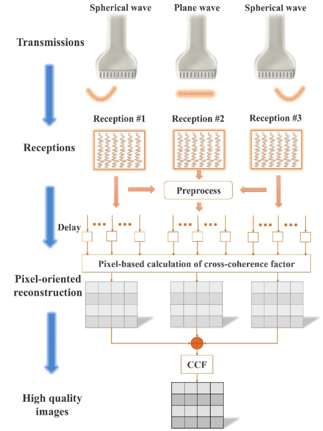
Methods: The proposed ultrafast ultrasound imaging framework with combined transmissions and cross-coherence-based reconstruction (US-CTCC) comprises three parts: combined transmissions, preprocessed backscattered signals, and coherence-based reconstruction.
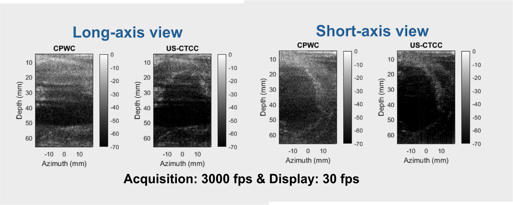
Results: The reduction of artifacts in our proposed ultrafast imaging framework US-CTCC led to a better delineation of an in vivo beating pig’s heart than coherent plane wave compounding (CPWC).
Reference: Y. Zhang, Y. Guo, and W.-N. Lee. "Ultrafast ultrasound imaging using combined transmissions with cross-coherence based reconstruction." IEEE transactions on medical imaging, in press,2017.
Example 2: Signal-to-noise ratio improvement
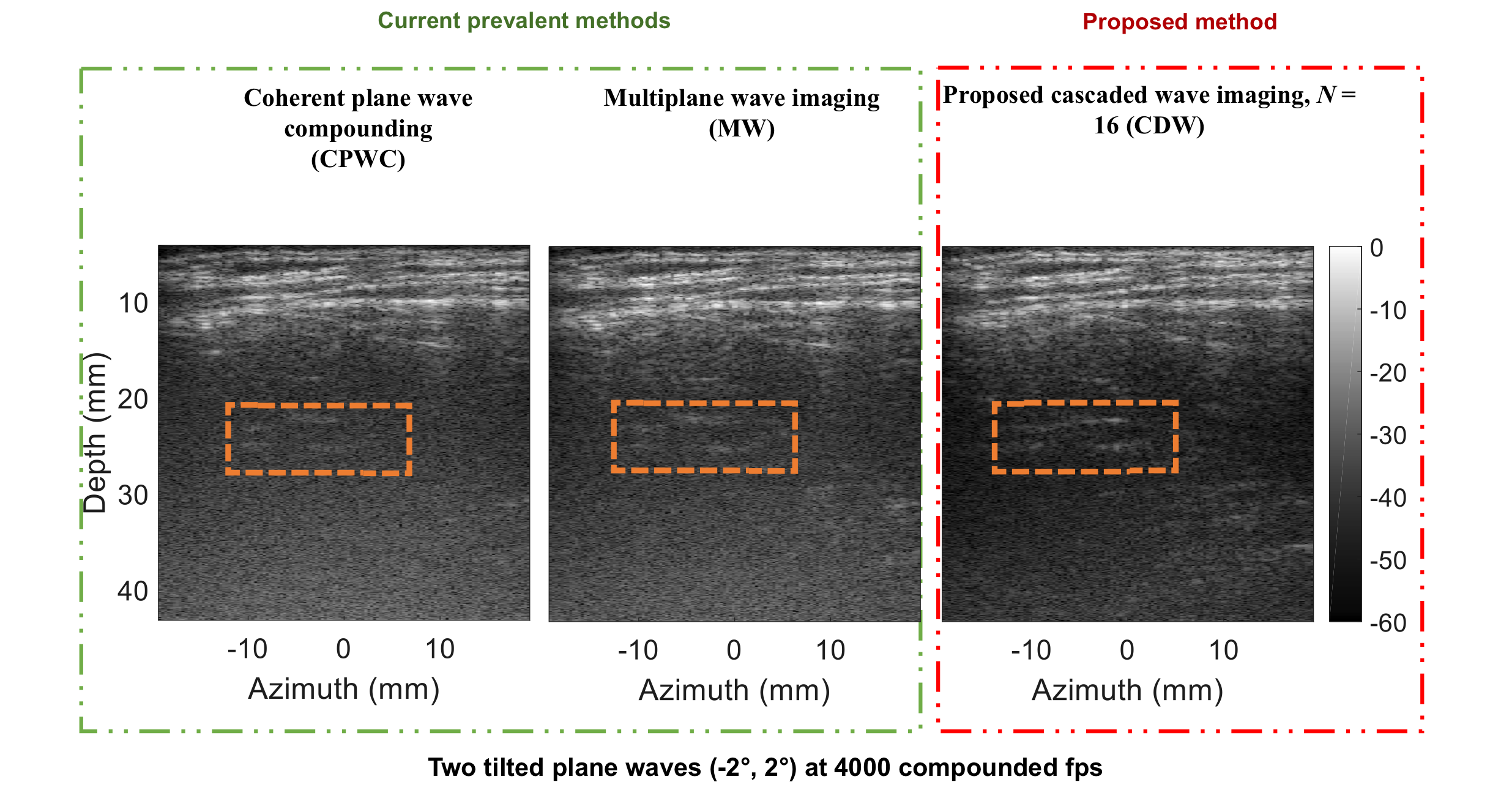
Description: The sonographic signal-to-noise ratio (SNR) of ultrafast imaging remains limited due to the lack of transmission focusing, thus insufficient acoustic energy delivery. We hereby propose a new ultrafast ultrasound imaging methodology with cascaded dual-polarity waves (CDW), which consists of a pulse train with positive and negative polarities. A new coding scheme and a corresponding linear decoding process were thereby designed to obtain the recovered signals with increased amplitude, thus increasing SNR without sacrificing the frame rate
Methods: The designed CDW imaging sequence consists of the transmission and reception parts. In transmission, each transmitted signal is a long pulse which contains N (N = 2k, k = 0, 1, 2,…) cascaded waves with short time intervals and +1 or -1 polarity coefficients, instead of the conventional short pulse with a single wave. In reception, a linear decoding scheme comprised of addition, subtraction, and delay operations is devised to recover N times higher intensity backscattered signals to gain SNR of 10·log10(N).
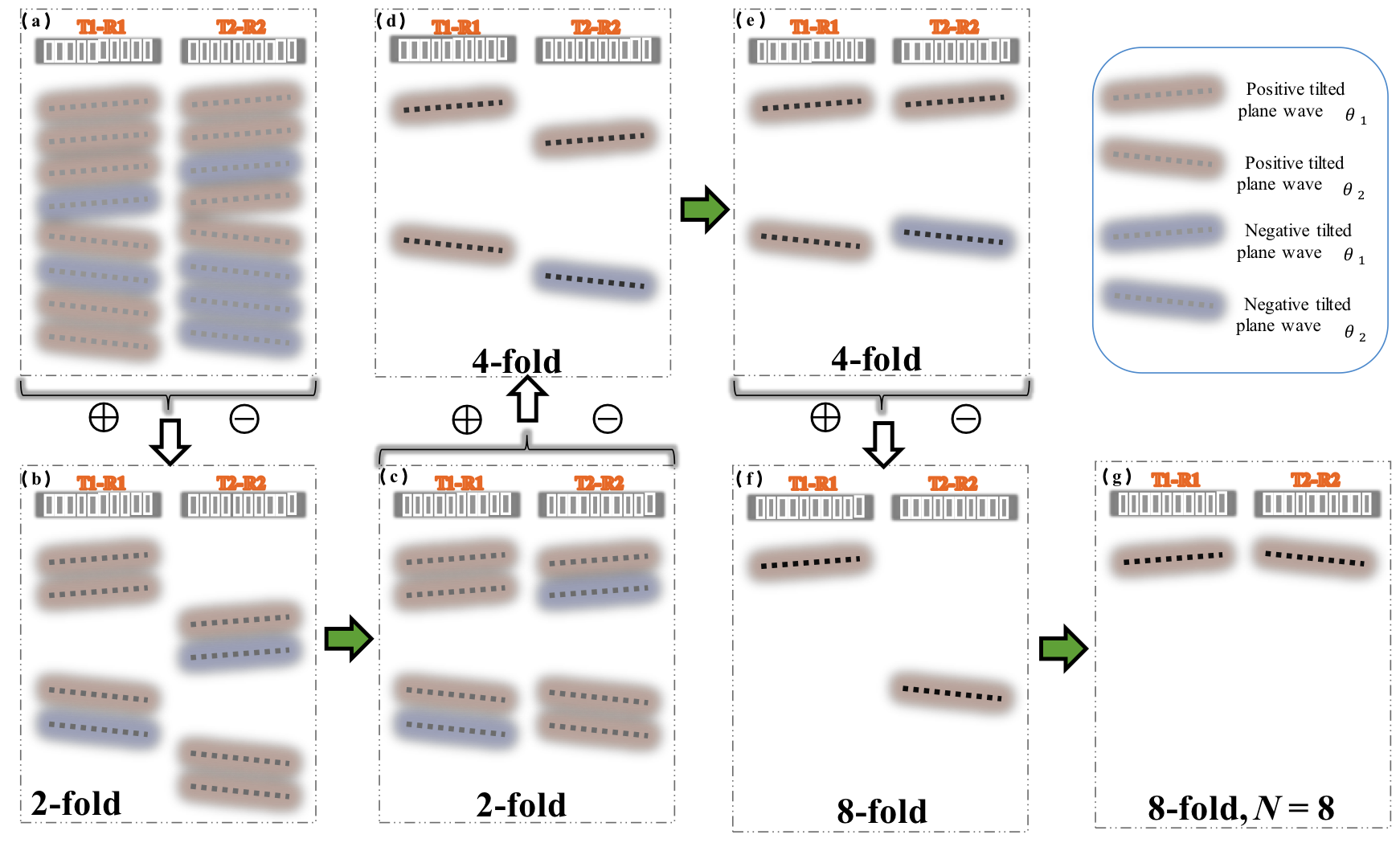
Results: The newly designed CDW ultrafast ultrasound imaging technique achieved higher quality in vivo human back muscle images than coherent plane wave compounding (CPWC) and multiplane wave (MW) imaging.